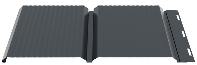
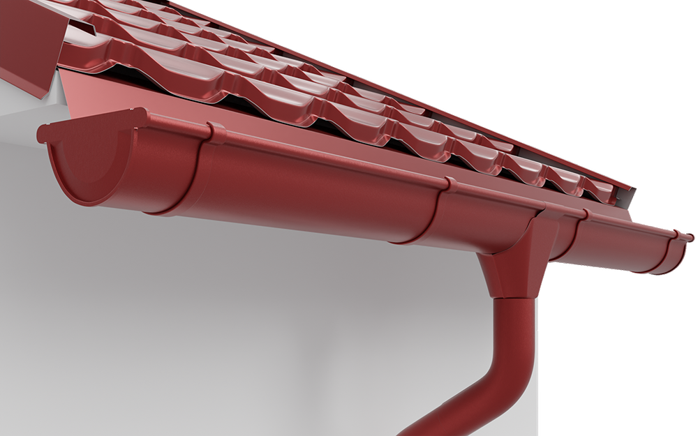
METAL 150 / 90
Ensures the collection of rainwater and its evacuation from any roof, regardless of its surface
SMART BENEFITS
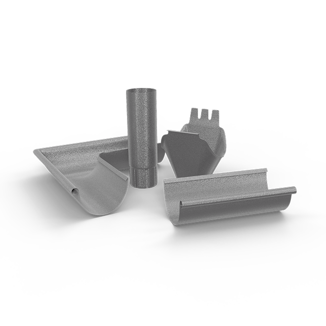
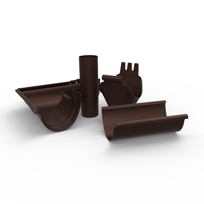
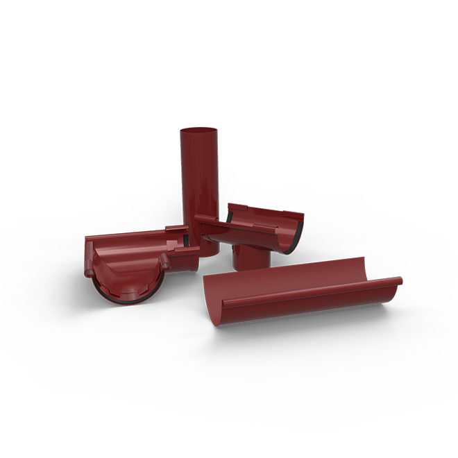
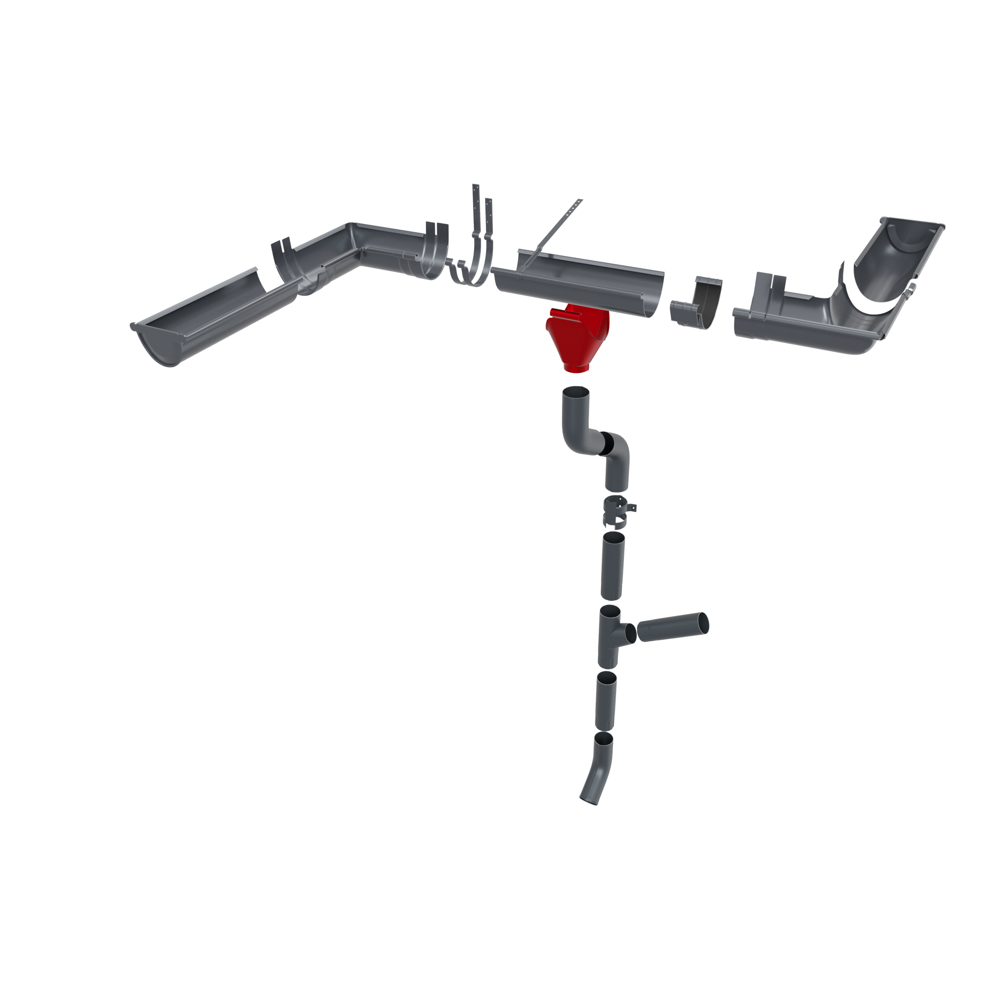
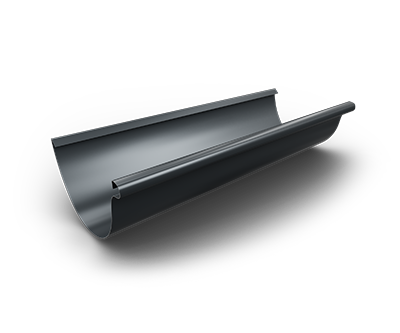
The SMART 150/90 gutter and downpipe system is designed for the efficient collection and drainage of rainwater from the roof, making it suitable for buildings with larger drainage surfaces or for areas with heavy rainfall.
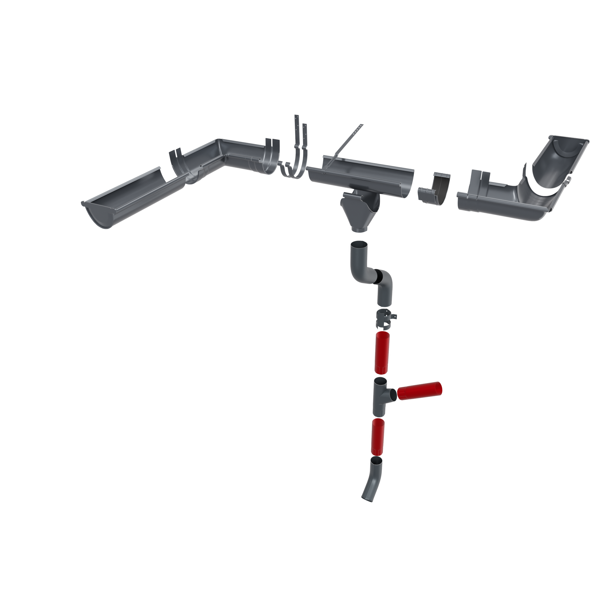
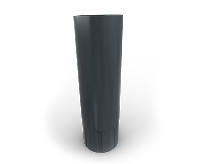
The system configuration includes metal gutters with a diameter of Ø150 mm and downpipes with a diameter of Ø90 mm. This combination provides a higher drainage capacity and is recommended for larger roofs or for situations where the volume of water collected by the gutter is high.
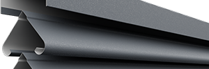
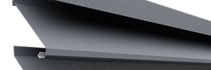
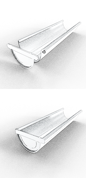
A distinctive feature of this roof gutter system is the special gutter design, which includes an inward-turned outer edge (internal wulst). Unlike traditional gutters, where the edge is oriented outward, this конструктиве solution reduces the risk of water overflow during heavy rainfall and allows the use of a larger effective gutter volume.
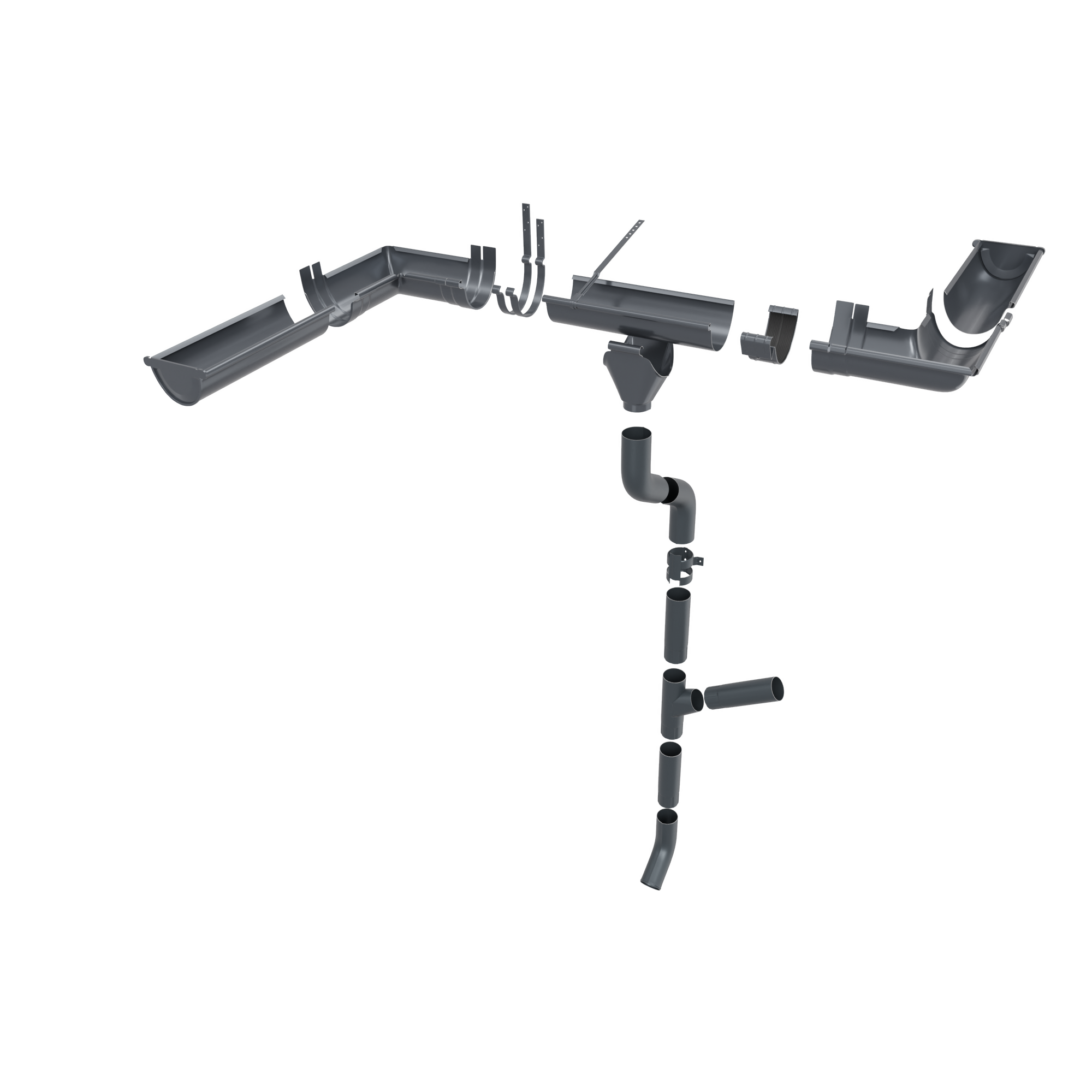
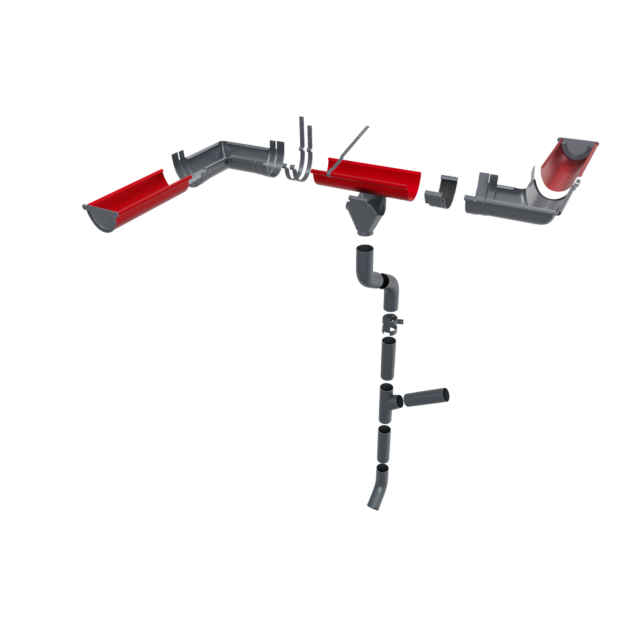
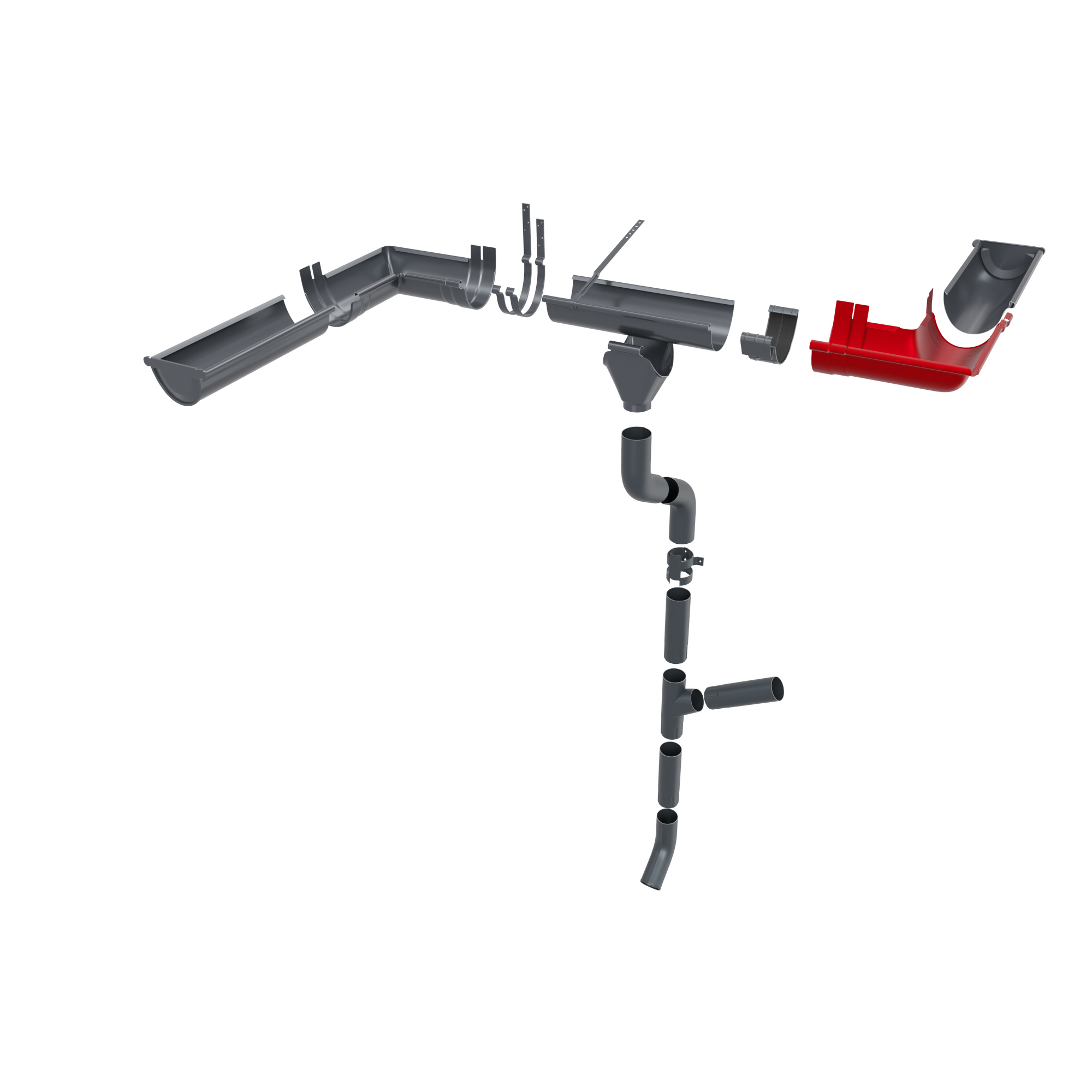
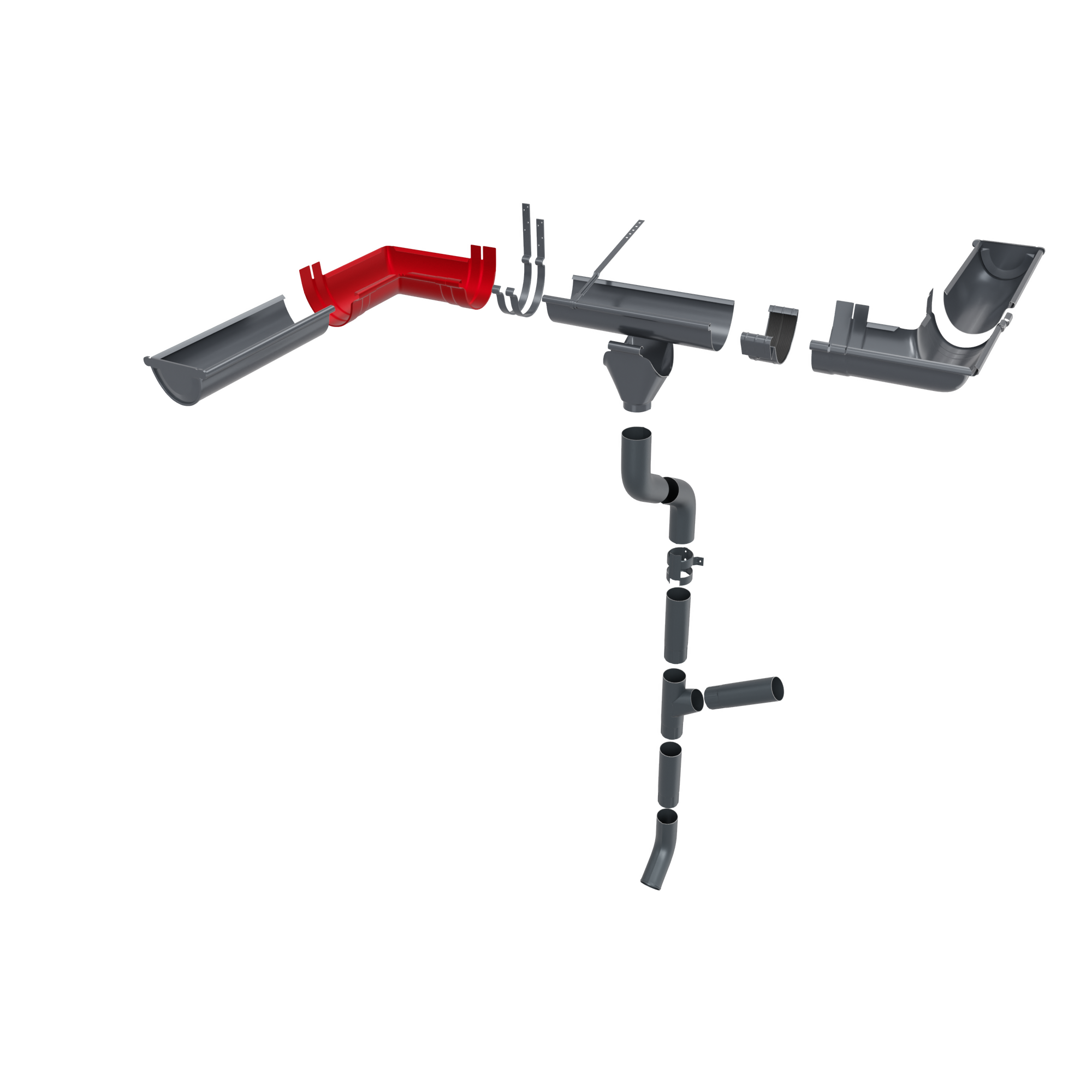
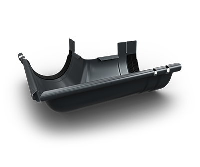
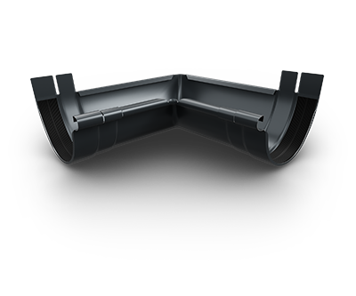
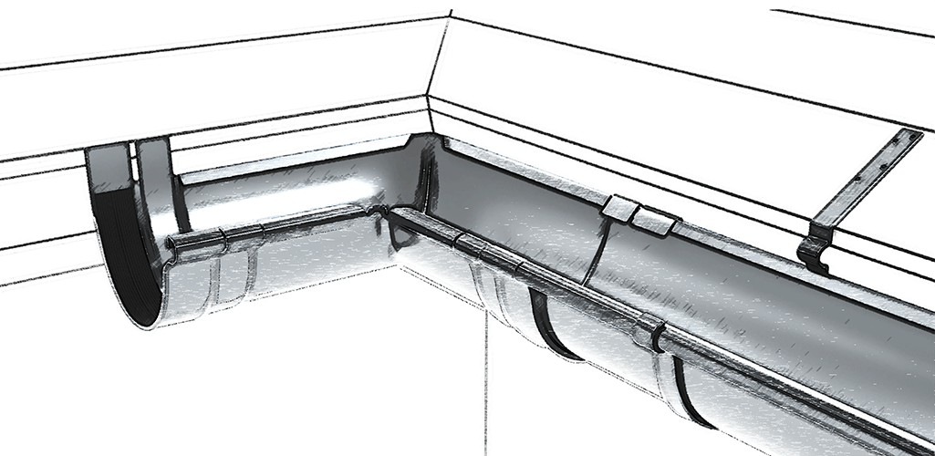
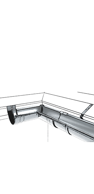
This design also offers important advantages during installation. The internal and external corners are designed with an integrated clamp and an overlap area of approximately 5 cm, which simplifies element alignment and eliminates the need for additional clamps. At the same time, this constructive solution avoids the use of additional support brackets in corner areas, where the available space is limited.
For optimal system performance, roof gutters should be installed with a slope of approximately 5 mm for each linear meter, directed toward the gutter–downpipe connection. In most cases, installing one outlet every 10 linear meters of gutter ensures efficient water drainage.
Like the other SMART systems, the components are manufactured from galvanized steel with multilayer protection, ensuring high corrosion resistance and a long service life.
Through the combination of high drainage capacity, optimized gutter design, and efficient installation, the SMART 150/90 gutter and downpipe system represents a high-performance solution for creating a rainwater drainage system for large roofs or areas with heavy rainfall.
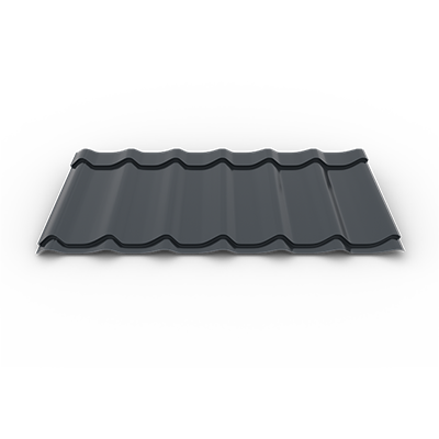
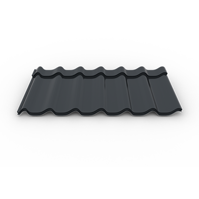
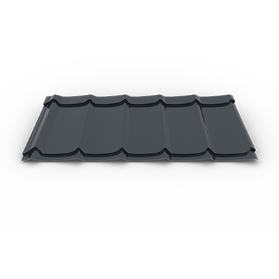
FINISHES & COLORS
Glossy
A durable polyester coating that provides excellent water resistance, preventing corrosion and ensuring long-lasting protection against moisture and weathering.


AluZinc
AluZinc offers superior protection, significantly outperforming zinc-coated steel in corrosion resistance, ensuring enhanced durability and longevity.

Double-coated matt


Displayed product colors could vary from one screen to another, according to the display's settings or filters used. For best accuracy please make sure that you ask a sales representative for a color plate sampler.
SMART INSTALLATION PRINCIPLES
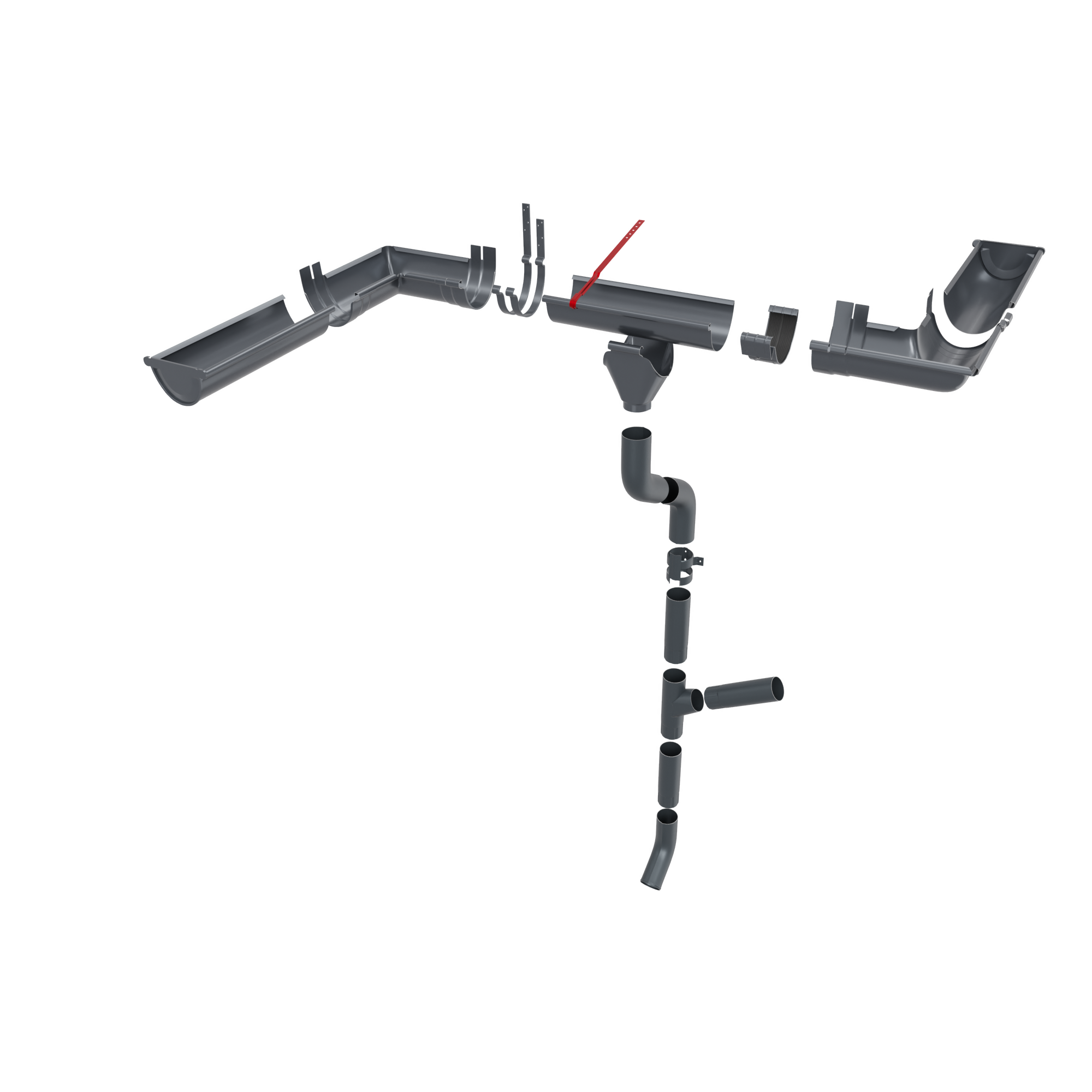
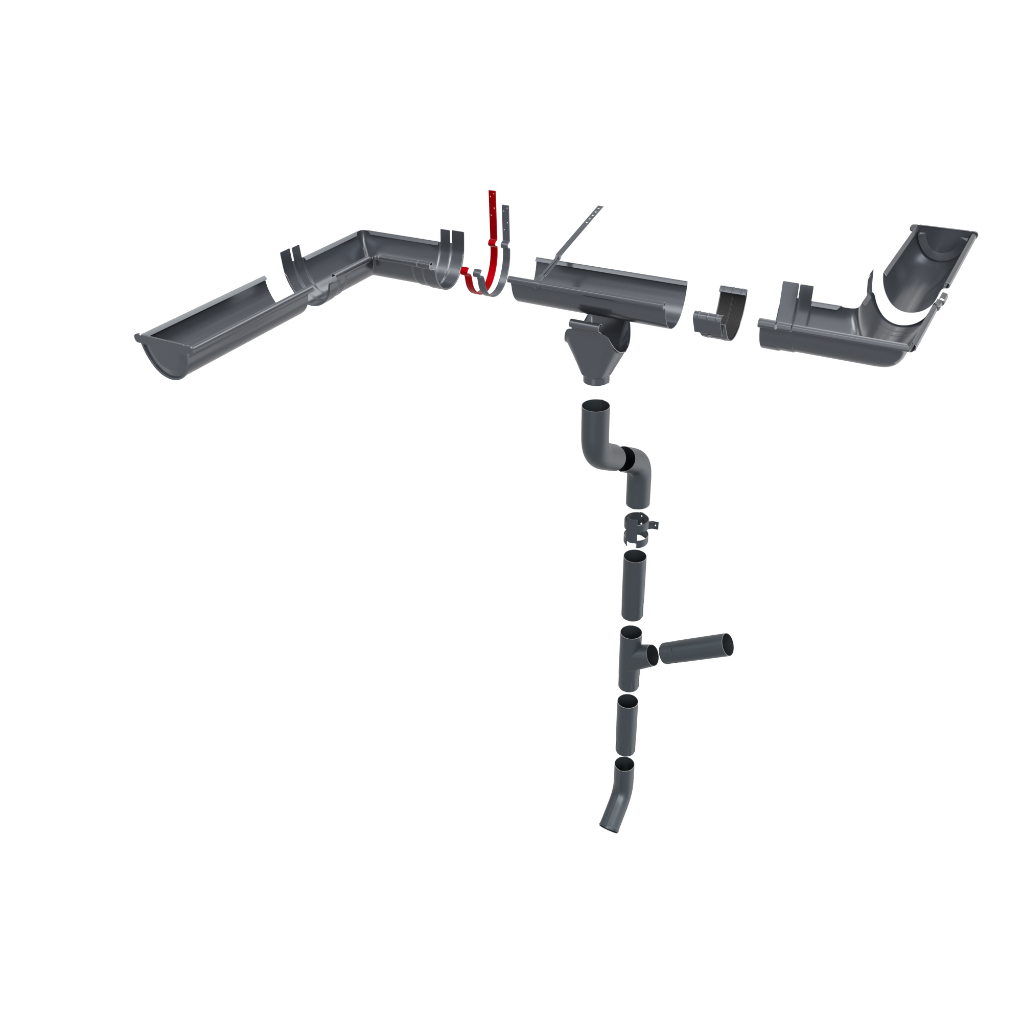
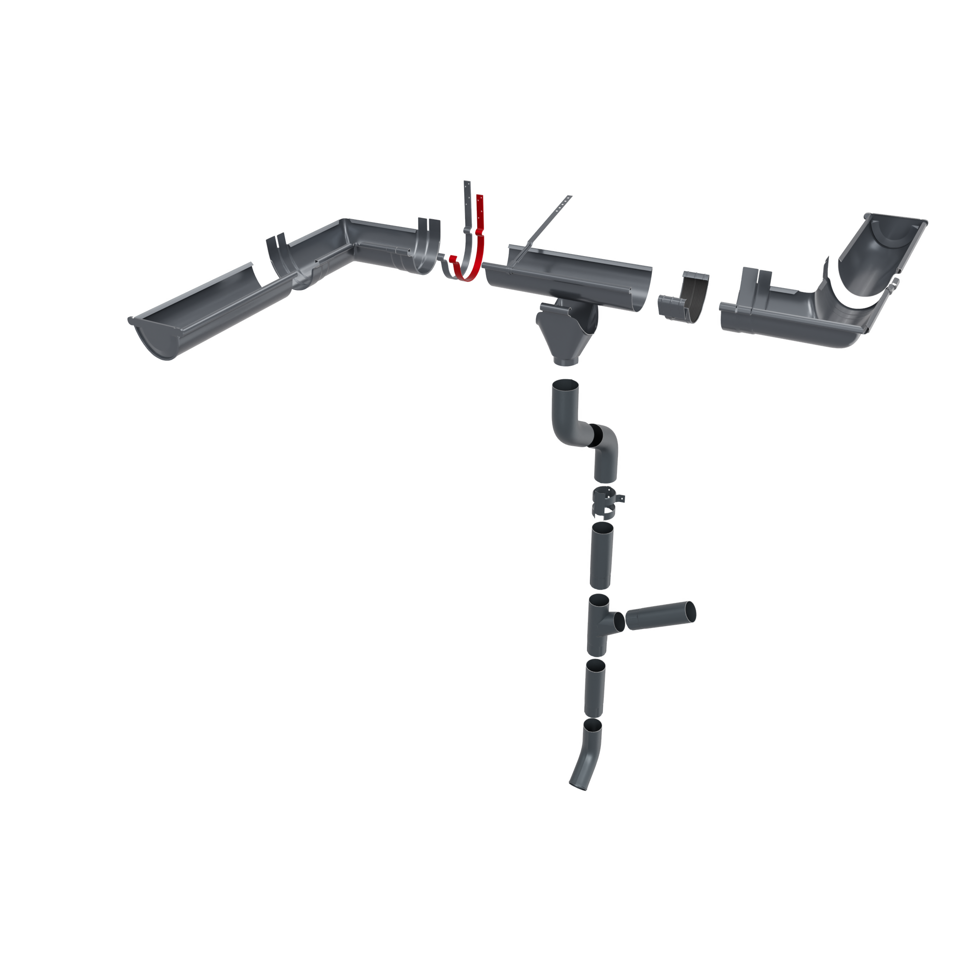
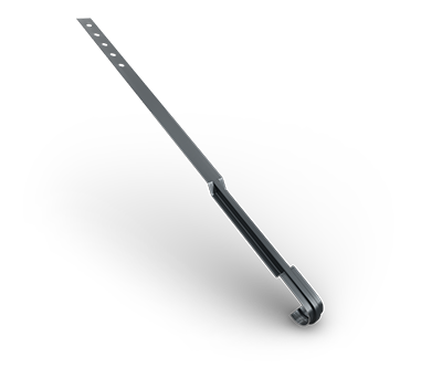
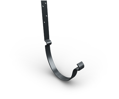
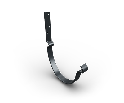
The tracing of the hooks is done taking into account 2.5 - 5 mm for each linear meter of eaves.
When mounting the hooks, a difference of 5 mm from the horizontal level will be taken into account, based on the internal locking pin of the hook.
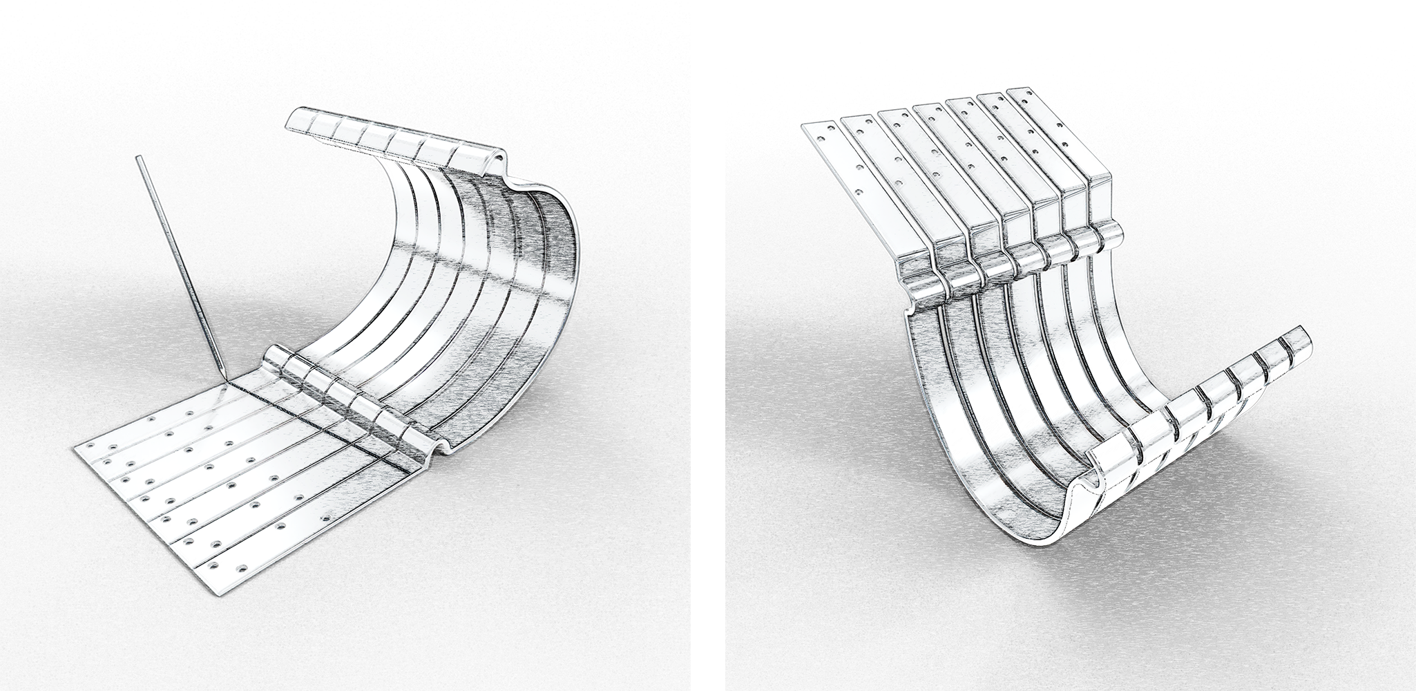
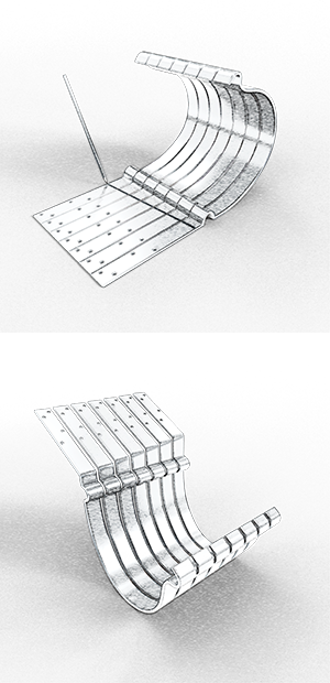
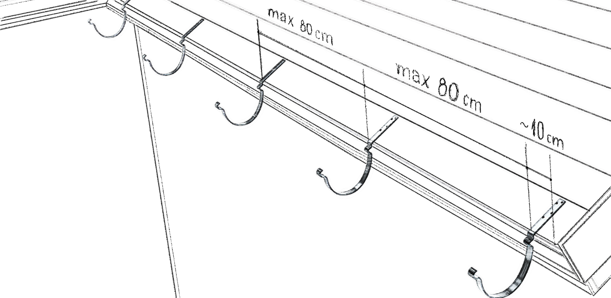
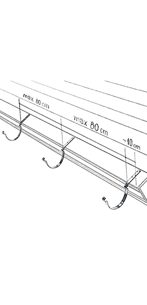
Before mounting the hooks, it is necessary to draw a drain slope towards the location of the downpipe. It is preferable for the trough slope to be about 2 mm every 1 linear meter. The distance at which the hooks are mounted will not exceed 80 cm, and the hooks at the ends will be 10 cm to the edge of the roof.
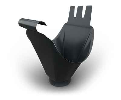
Position the gutter in the hooks and mark with a pencil the location of the outlet collar. Using the joint, mark the contour of the connection on the gutter and then, with the help of the hacksaw, cut it into a “V”.
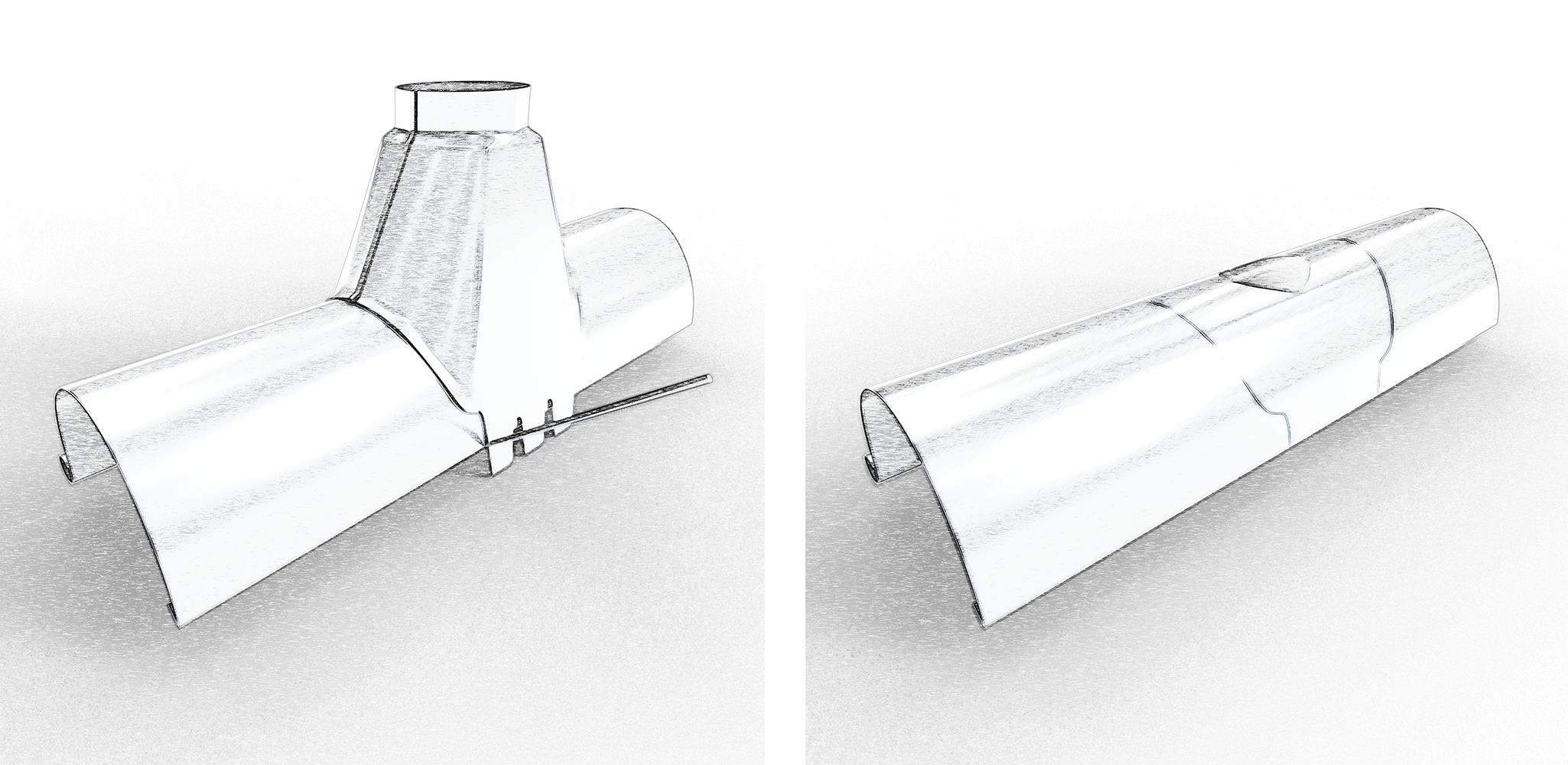
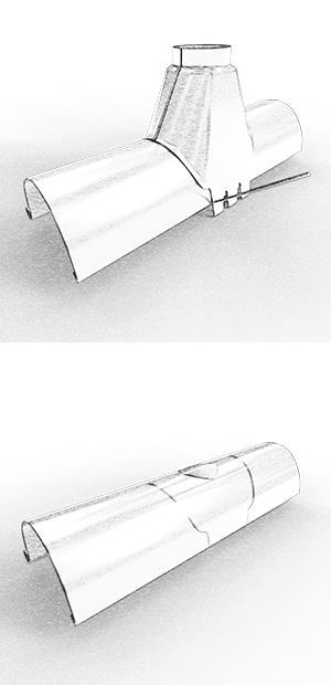
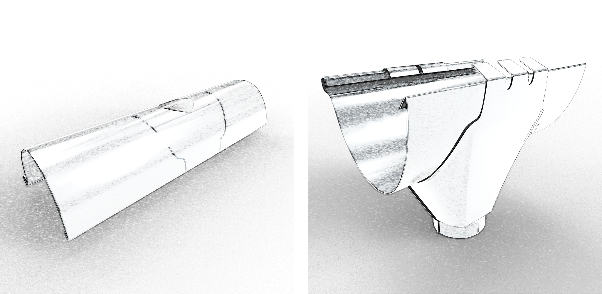
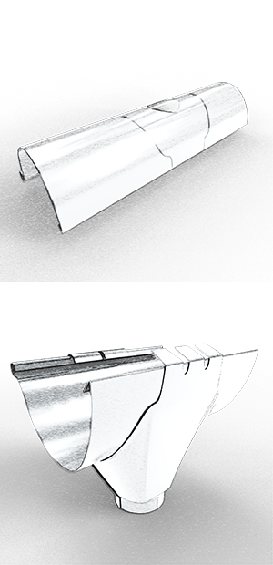
Using a sheet metal scissors, cut a hole with a diameter of 85 mm, taking as a reference point the center drawn with the help of the joint, then, with the help of a rubber hammer, gently tap the edge of the cut. Push the bent edge of the gutter-pipe connection into the gutter, then push the connecting piece back and secure the securing straps inside the gutter.
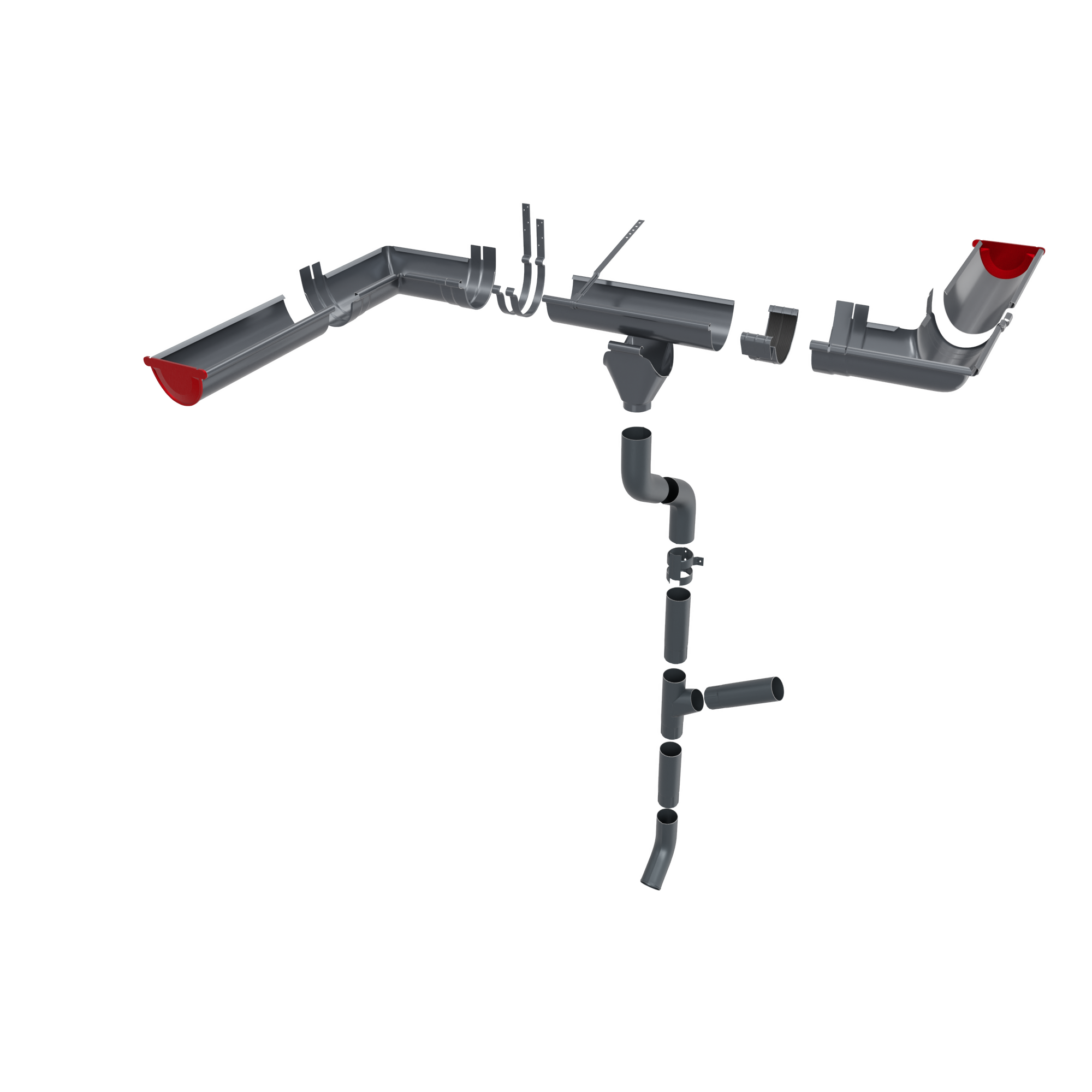
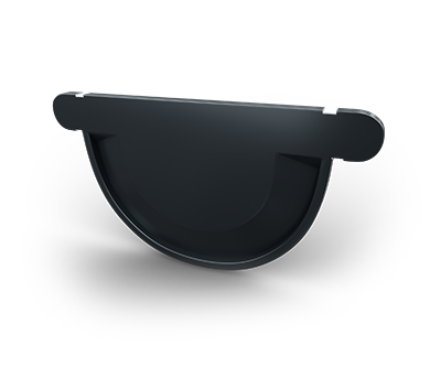
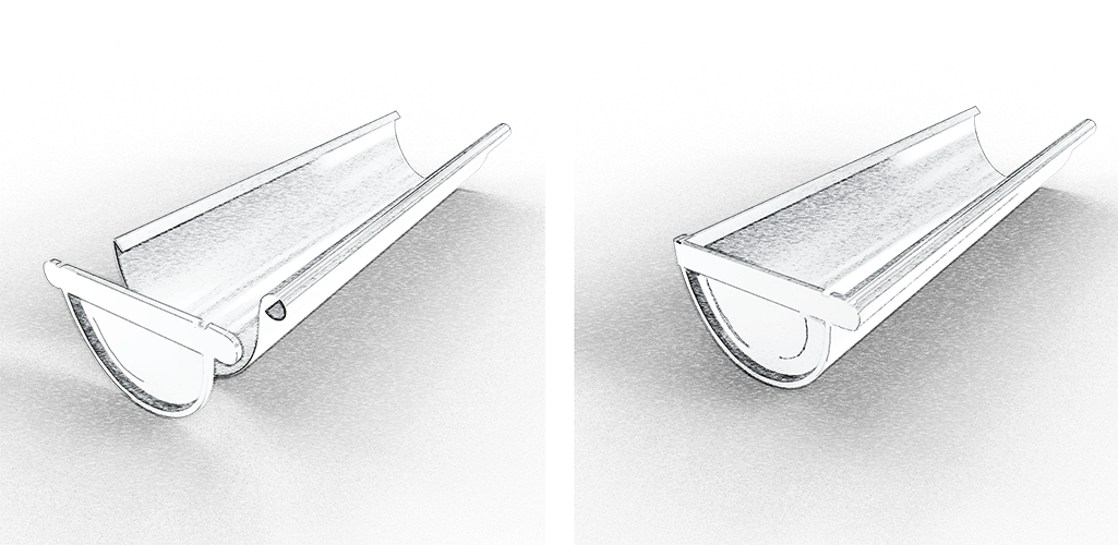
Attach the cover to the edge of the gutter by lightly pressing it with your hand, making sure that its circumference coincides with the mounting channel in the cover. Then tap the lid with the palm of your hand, or lightly with a rubber mallet, until it completely enters the gutter.
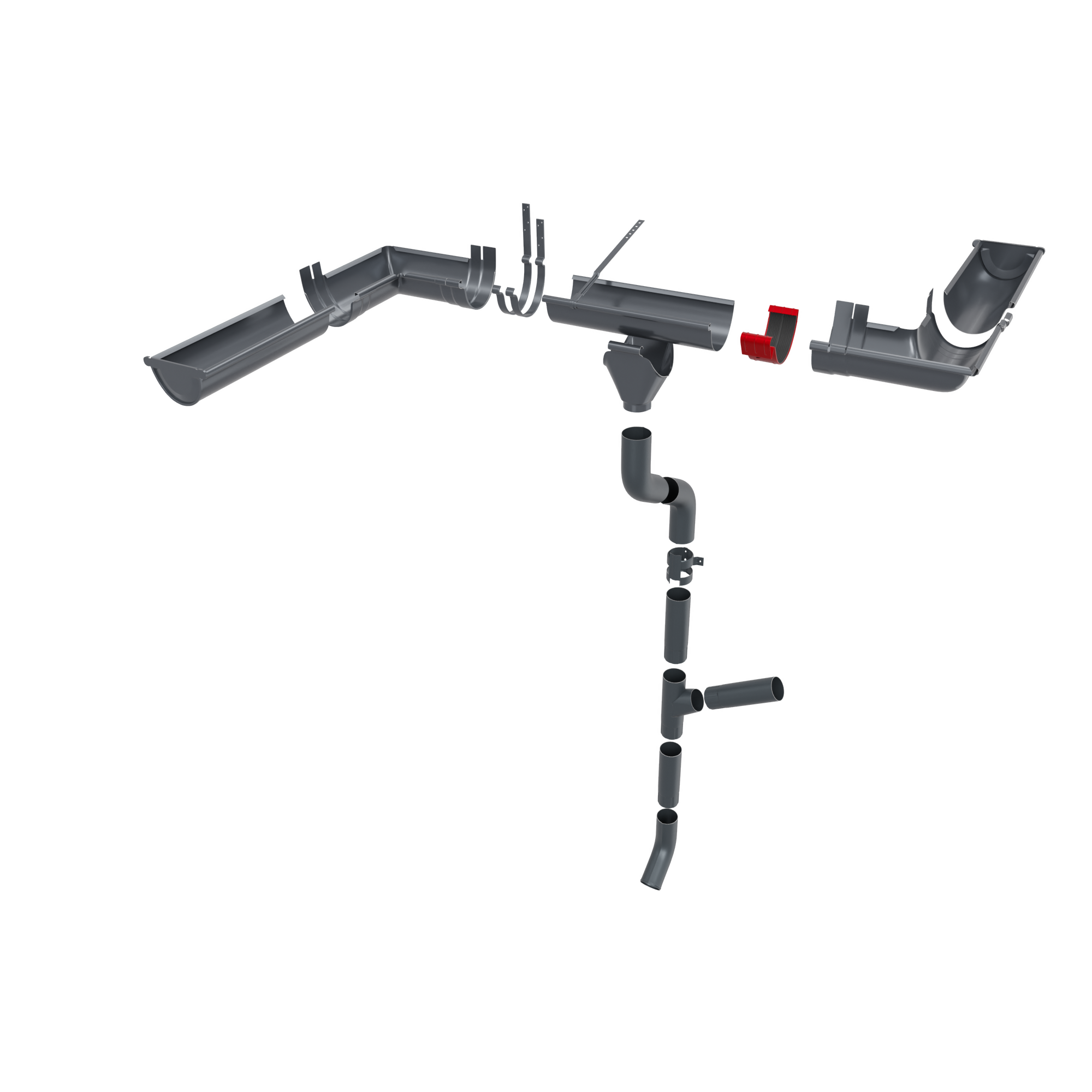
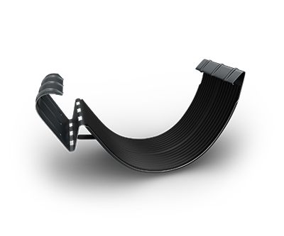
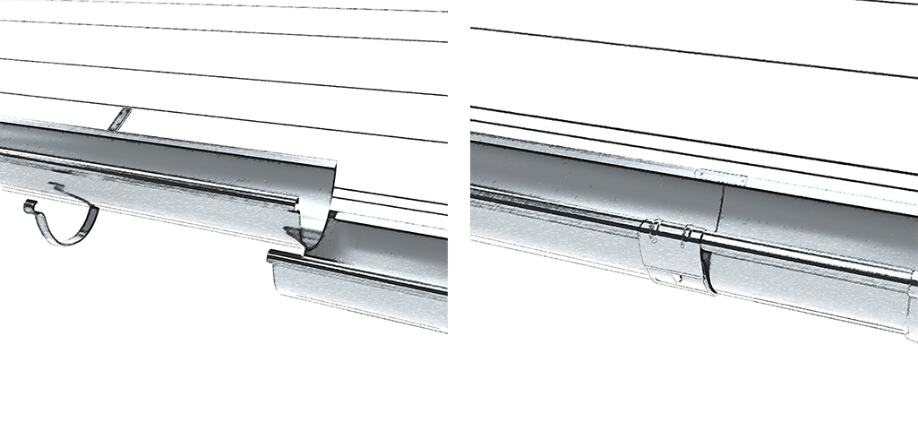
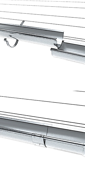
The joining of the gutter sections is done either by the end-to-end assembly of the sections - using the gutter joint (to provide increased strength and rigidity to the joint), or by overlapping. After the butt assembly, the gutter bracelet will be applied, on which, previously, a sealant (silicone) will be applied.
The inner and outer corners are fixed by connections to the gutters (gutter brackets).To ensure the bending strength of the connection, at the end of the gutter and the corners, the fastening element will be inserted before mounting or they can be superimposed using silicone between the two overlapping elements.
After finishing the drilling process, align the fixing holes of the Horizontal "U" Profile with those of the Vertical "U" Profiles and the Back Support Profile.
Insert the pop-rivet into the rivet gun.
Place the Rivet Gun perpendicular to the hole and rivet them in the fixing points drilled in the previous step.
Keep the profiles firmly in place, throughout the riveting process, to avoid their repositioning.
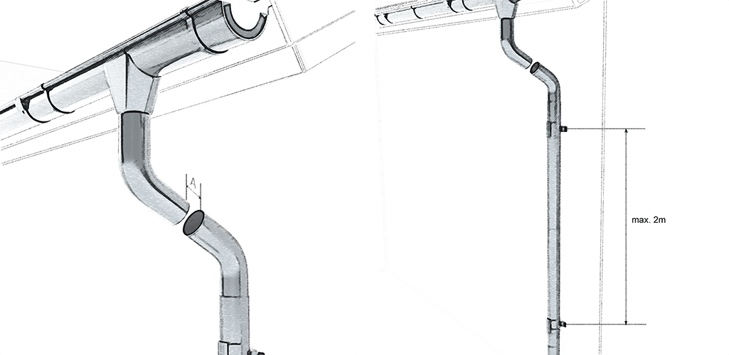
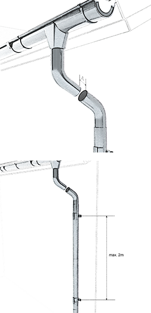
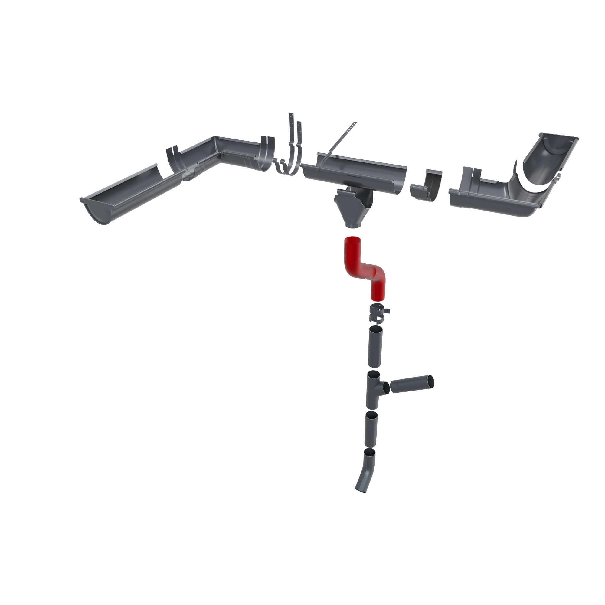
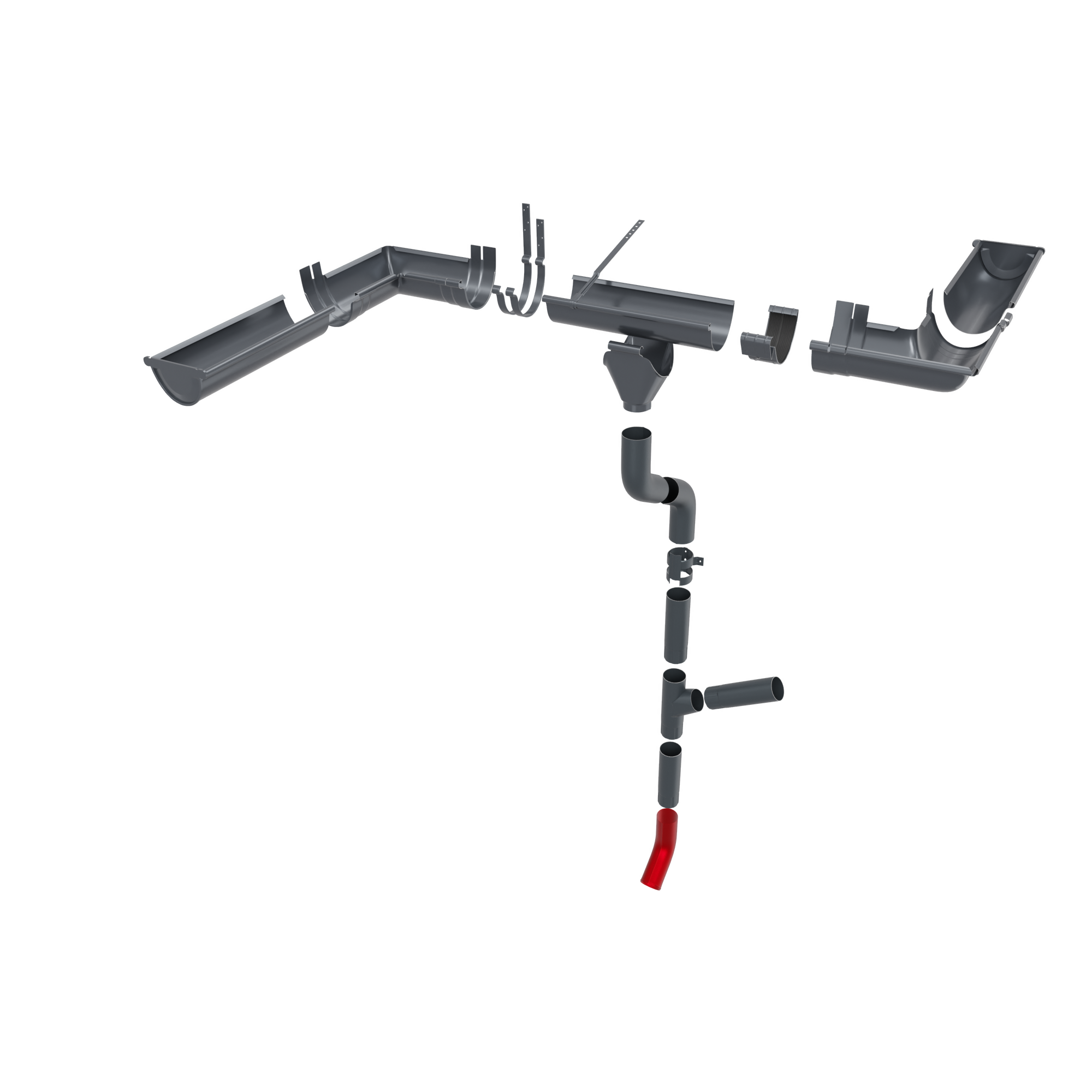
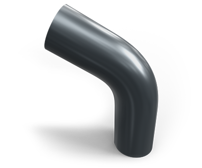
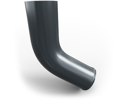
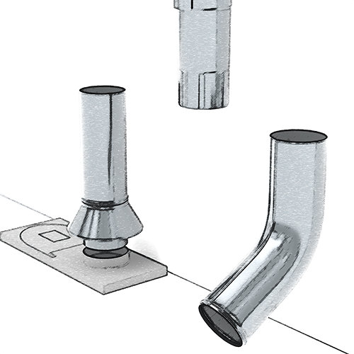
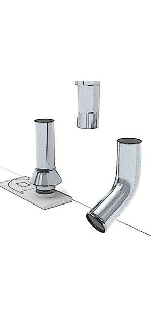
The bending end tube is installed when the pipe is not connected to a sewer system.
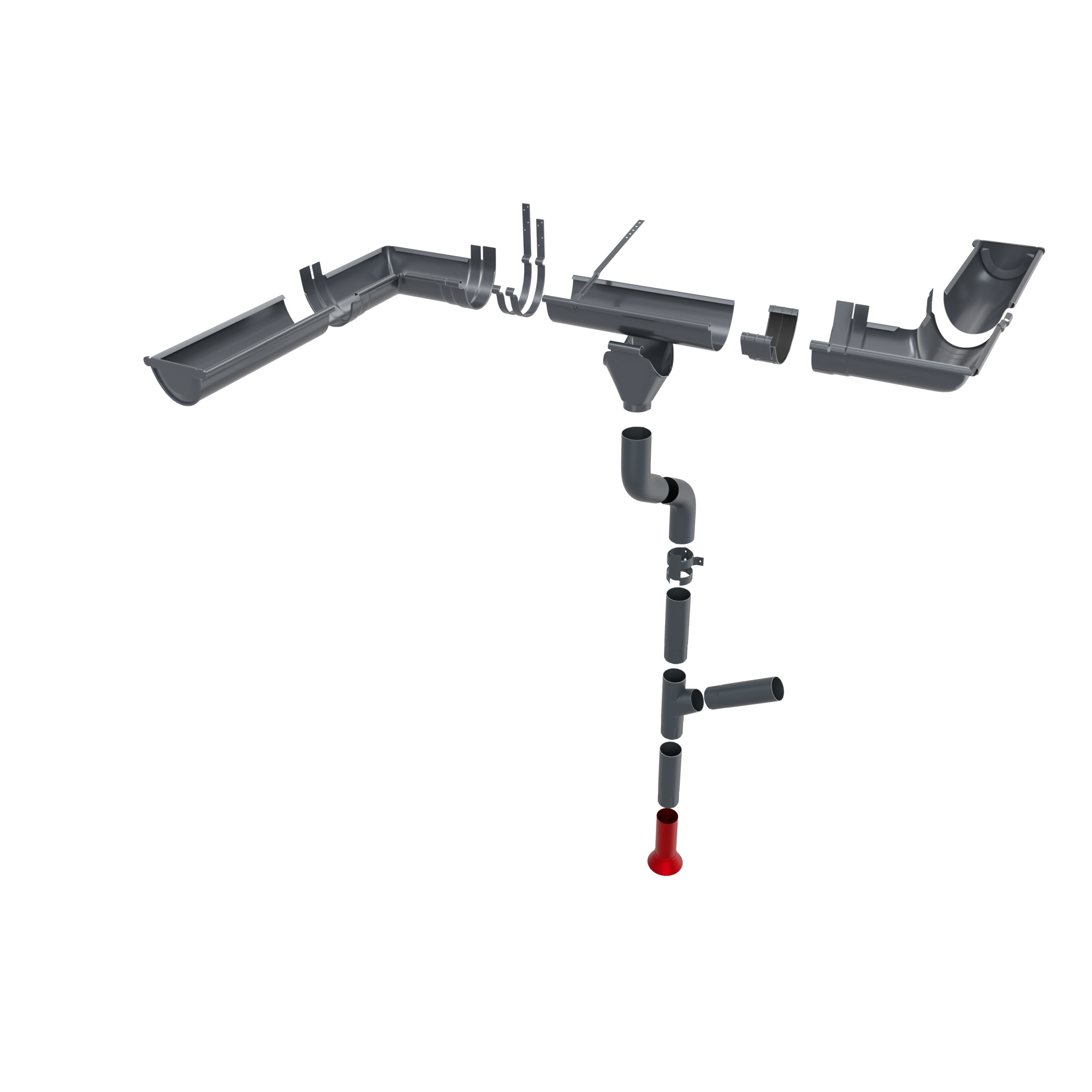
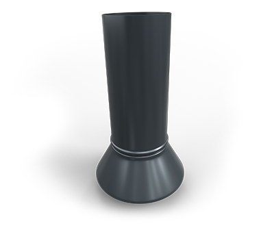
The sewer connection is a connecting element between the downpipe and the sewer system.
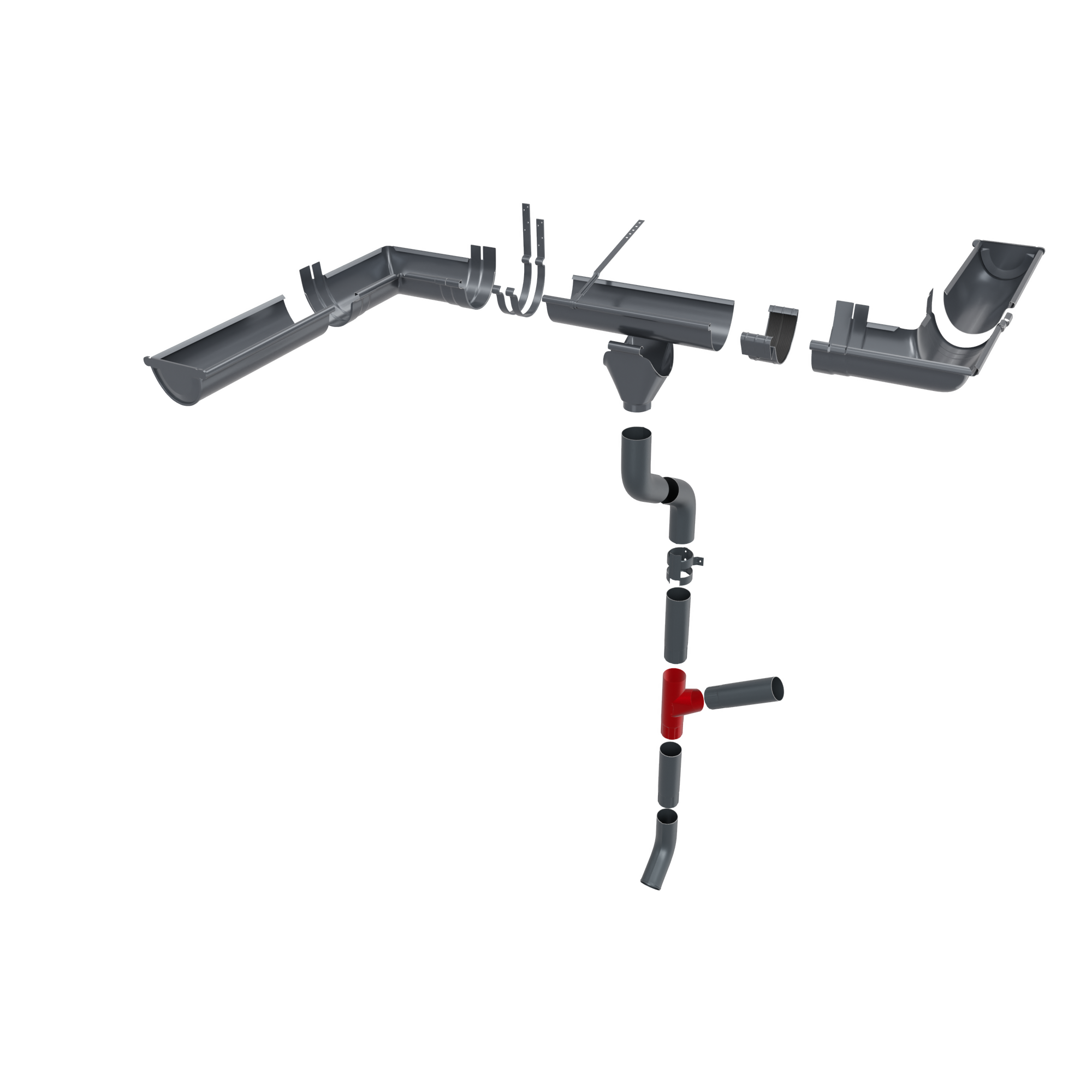
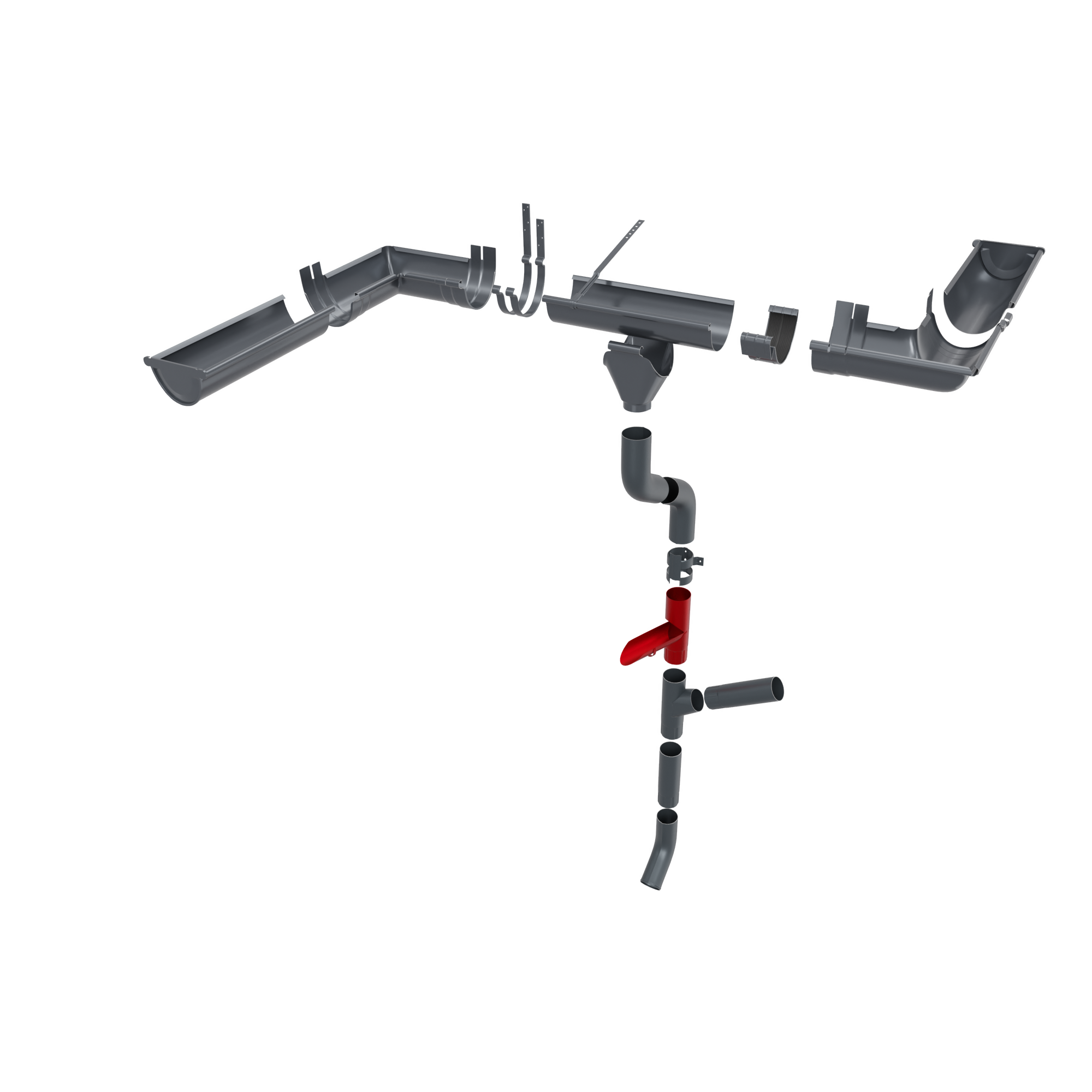
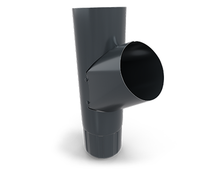
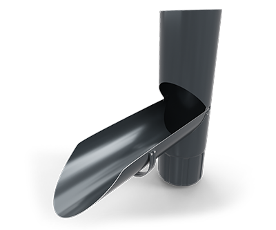
The damper connection is installed on the pipe so that the water can be diverted to the outside.
The Y pipe connection connects two different pipes to the same outlet.
SMART VIDEO INSTALLATION GUIDE