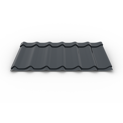
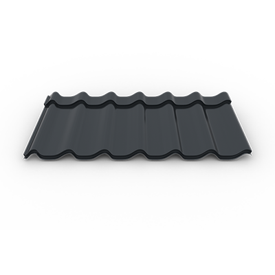
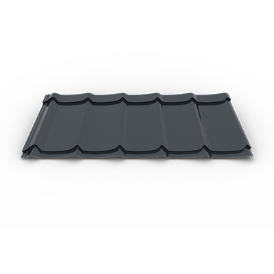
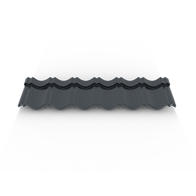
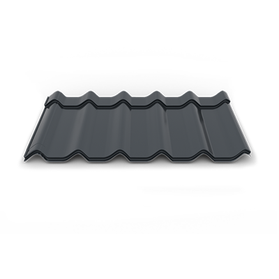
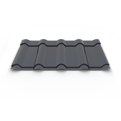
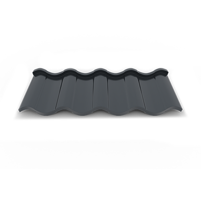
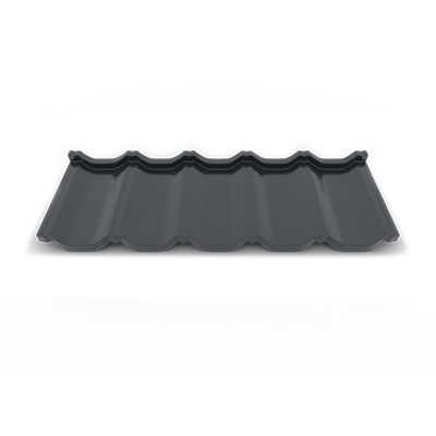
SIGMA

Easy to install, ZERO maintenance, formidable endurance over time

SMART BENEFITS

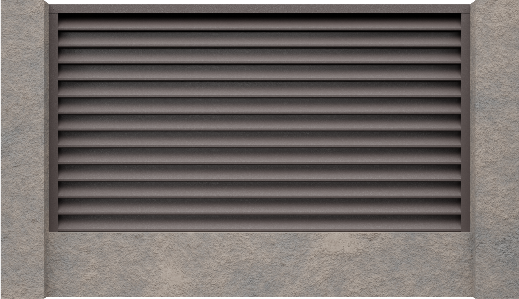
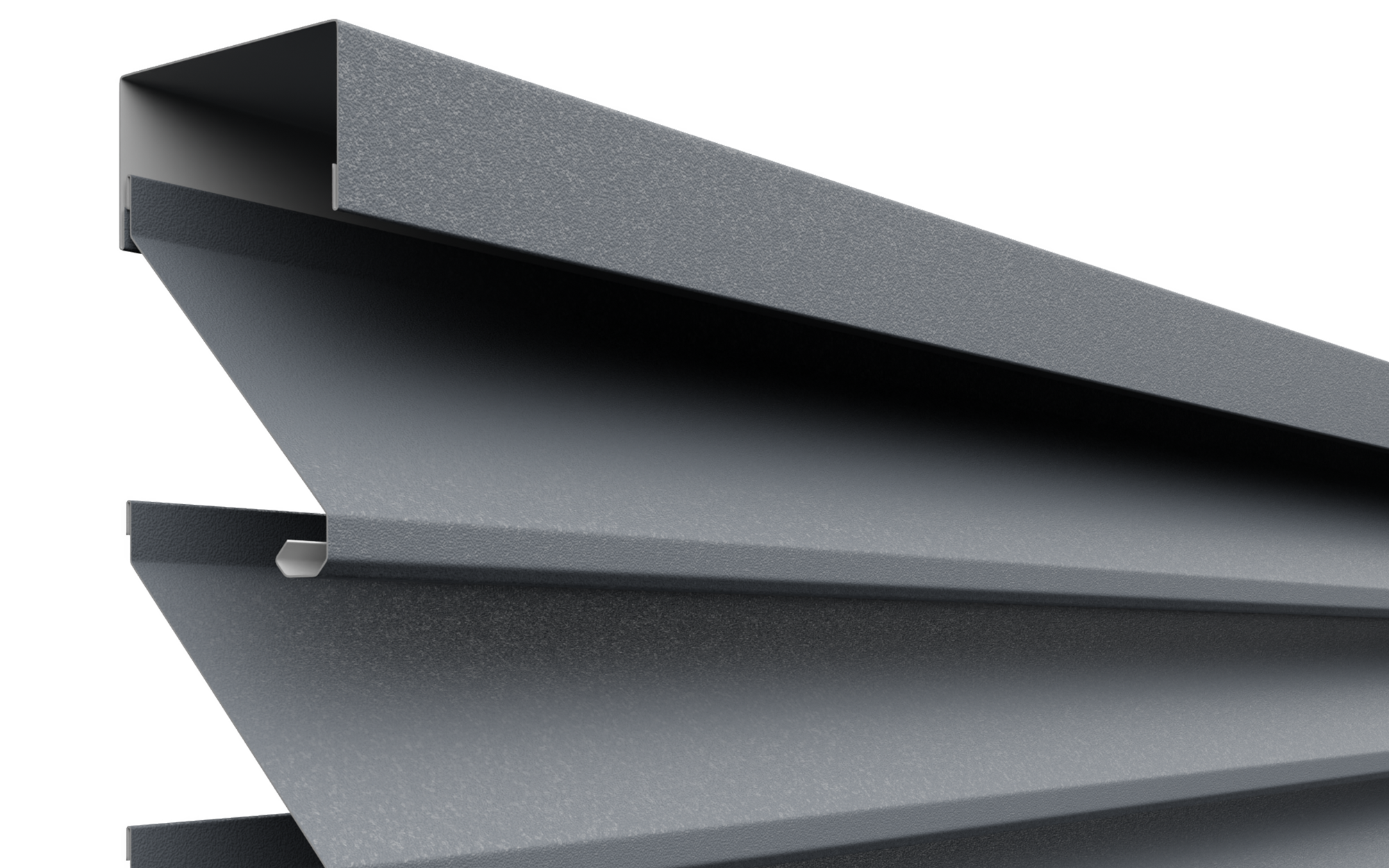
Made of quality steel sheet (the same raw material used in the production of metal tiles), the blind fences have guaranteed anti-corrosion and aesthetic properties and are weather and UV resistant.

The raw material used allows the blinds to withstand climatic loads between -50°C and +120°C.

They have an anticipated lifespan of over 50 years.

Quick and easy assembly Quick and easy assembly which can be carried out by the customer without the help of a professional

Rigidity adapted to the profile type Rigidity adapted to the profile type

Minimum maintenance Minimum maintenance (no regular interventions: painting, varnishing, treatments against insects, sun or humidity)
Possibility of customization Possibility of customization (sizes / colors)
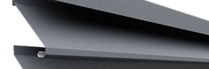
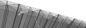
Air Flow Thanks to the design and positioning of the profiles, they allow free air circulation and eliminate the greenhouse effect

UV 15 YEARS Will maintain their color and will not fade, even after 15 years
FINISHES & COLORS

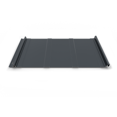
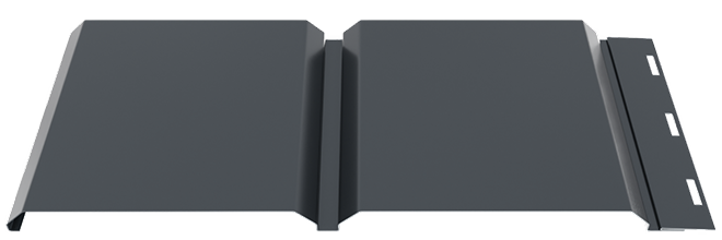
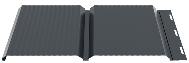
SIGMA

High Matt

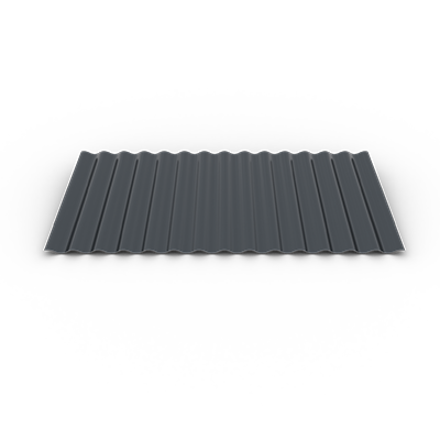
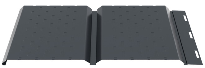
Finish with a 40-micron polyester paint layer, 5 microns thicker than the standard finish. The 3D textured surface provides a distinctive appearance and a pronounced matt finish.

Displayed product colors could vary from one screen to another, according to the display's settings or filters used. For best accuracy please make sure that you ask a sales representative for a color plate sampler.

TECHNICAL SPECIFICATIONS

SIGMA
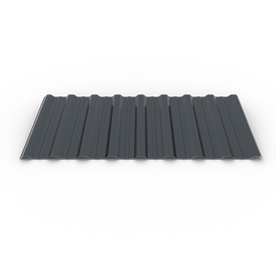
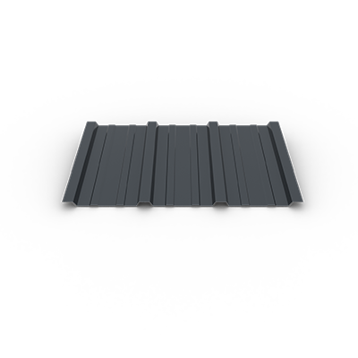
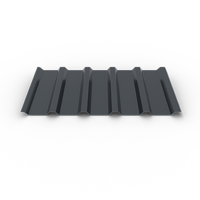
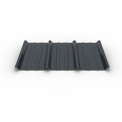
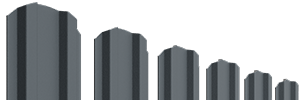
  • Total length of a blind profile max. 2000 mm
  • Total height of a blind profile 99 mm
  • Total width of a blind profile 30 mm

SMART INSTALLATION PRINCIPLES

step 1 INSTALLATION OF VERTICAL “U” PROFILES

Concrete or Brick Pillars

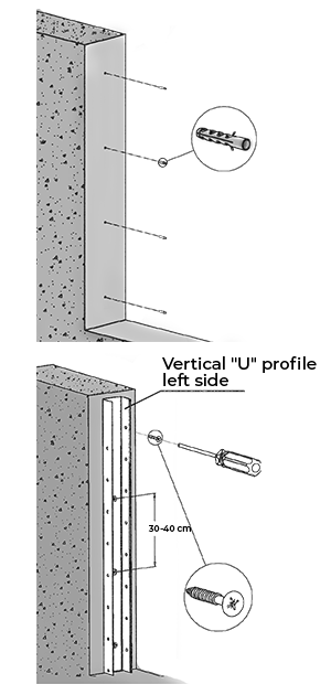
Position the Left Vertical "U" Profile on the post so that the opening hole of the profile is oriented towards the panel.
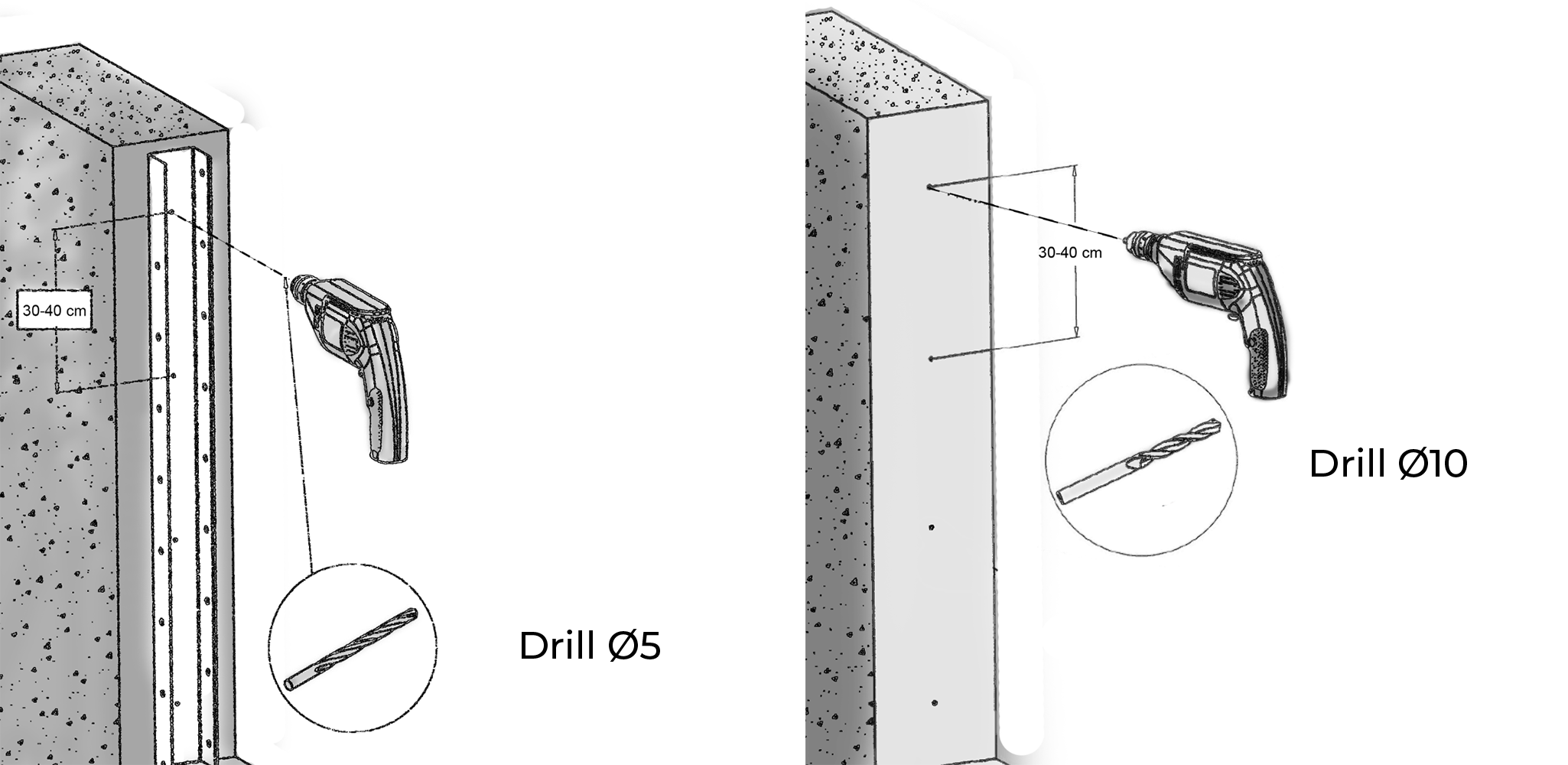
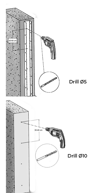
Maintaining the position of the Left Vertical "U" Profile on the post, use a drilling machine with a ⌀5 drill, designed for perforating metal, drill the Vertical "U" Profile towards the post in steps of 30-40cm.
After finishing the drilling process, remove the Vertical "U" Profile from the post.
You will notice the reference points (in 30-40 cm increments) that will serve as markings for drilling the post in the next step.
Using a drilling machine with a ⌀10 drill designed for perforating concrete, drill the post following the marking.
REPEAT THE ABOVE STEPS TO INSTALL THE RIGHT VERTICAL "U" PROFILE

step 2 INSTALLATION OF VERTICAL “U” PROFILES

Concrete or Brick Pillars

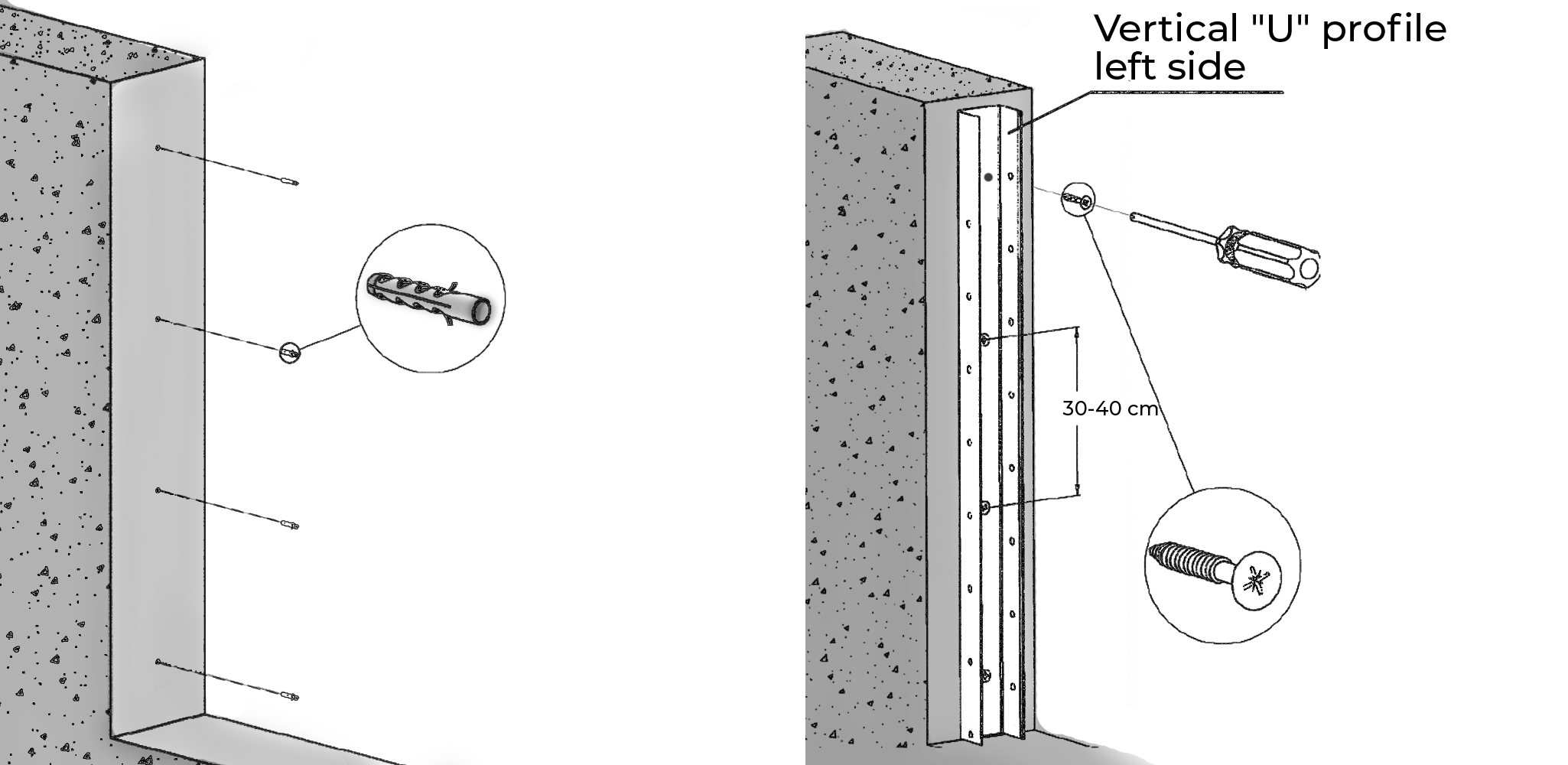
Insert the dowels into the holes in the post, drilled in the previous step.
Position the Left Vertical "U" Profile on the post. Make sure that the fixing holes of the post and those of the Vertical "U" Profile are aligned.
Using a Star or PH2 screwdriver, insert the dowel screws into the aligned holes and fix tightly by screwing.
Keep the profile firmly in place, through out the screwing process, to avoid its repositioning.

REPEAT THE ABOVE STEPS TO INSTALL THE RIGHT VERTICAL "U" PROFILE

step 3 INSTALLATION OF VERTICAL “U” PROFILES

Metal Pillars

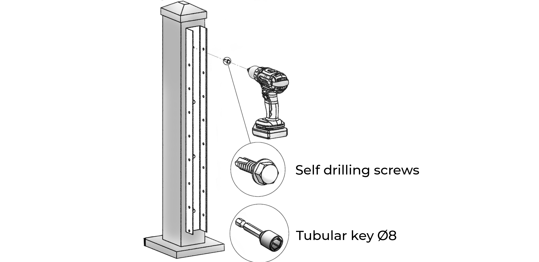
Position the Left Vertical "U" Profile on the post so that the opening hole of the profile is oriented towards the panel.

Using the Screwdriver Machine with the ⌀ 8 tubular key designed for perforating metal, screw the Vertical "U" profile of the post in steps of 30-40cm with self-drilling screws.
It is not necessary to distance the Vertical "U" Profile from the base.
Using the Screwdriver Machine with the ⌀ 8 tubular key designed for perforating metal, screw the Vertical "U" profile of the post in steps of 30-40cm with self-drilling screws.
Keep the profile firmly in place, throughout the drilling process, to avoid its repositioning.

REPEAT THE ABOVE STEPS TO INSTALL THE RIGHT VERTICAL "U" PROFILE

step 4 INSTALLATION OF BLINDS PROFILES

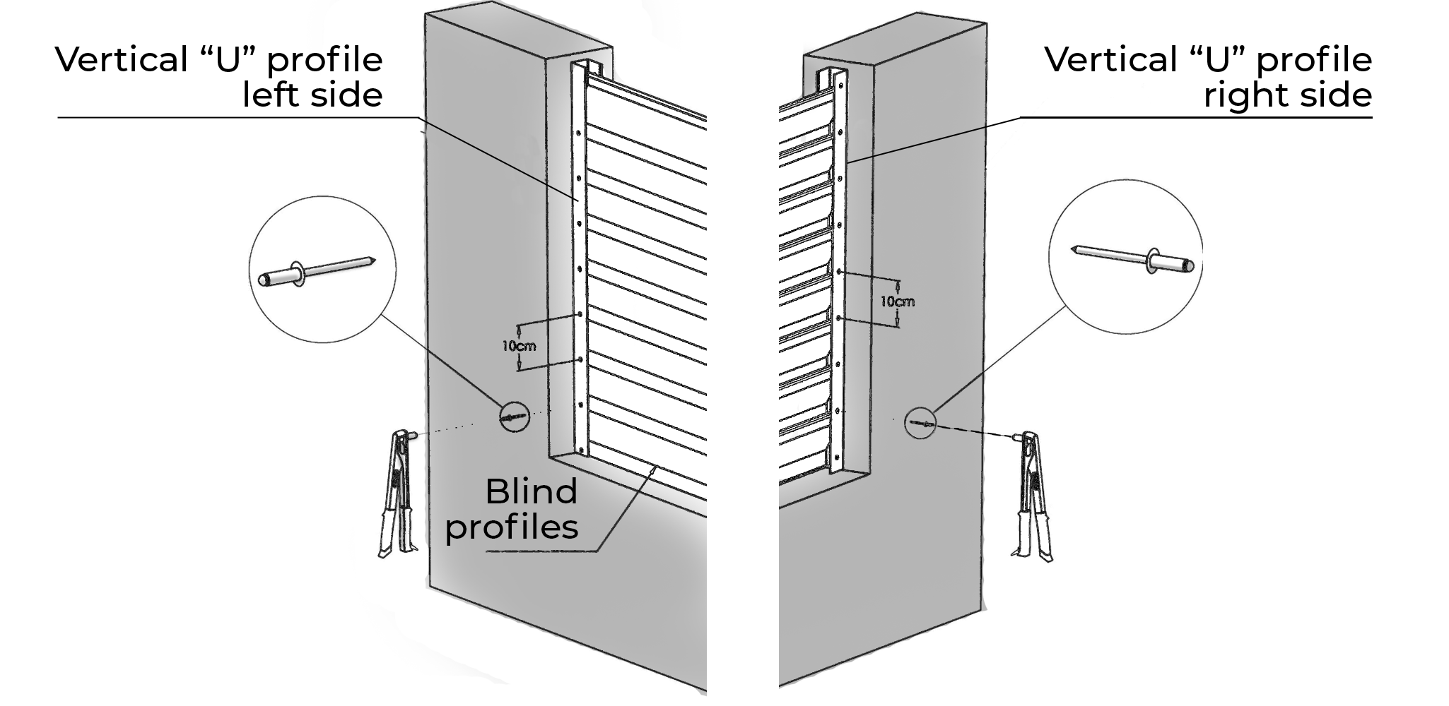
Start assembling the Blinds Profiles from bottom to top.
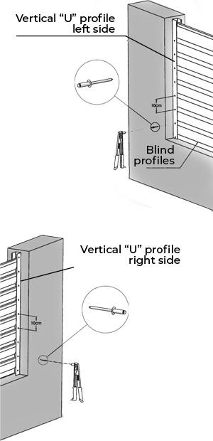
Position the Blinds Profile between the Vertical "U" Profiles.
Using the Drilling Machine with a ⌀ 5 drill designed for metal, drill the Blinds Profiles through the pre-made factory holes of the Vertical "U" Profiles.
Align the fixing holes of the Blind Profiles and the Vertical "U" Profiles. Insert the pop-rivet into the pliers / rivet gun. Place the Pliers / Rivet Gun perpendicular to the hole and rivet it in the 4 pre-drilled fixing points:

  • 2 in front (left + right)
  • 2 in back (left + right).

REPEAT THE ABOVE STEPS TO INSTALL ALL BLINDS PROFILES

step 5 INSTALLATION OF THE BACK SUPPORT PROFILE

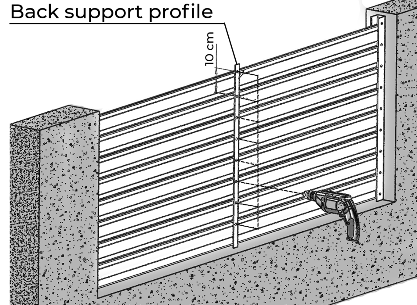
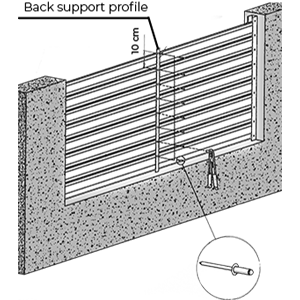
Position the Back Support Profile behind the panel, in the middle.

Using the Drilling Machine with a ⌀ 5 drill designed for metal, simultaneously drill the Back Support Profile towards the back of each Blind Profile, in the middle.

We recommend starting the drilling process with the first and last row of the Blinds Profile, then continuing with the perforation of the middle rows.

Hold the Back Support Profile firmly in place throughout the drilling process to avoid its repositioning.

step 6 INSTALLATION OF THE BACKSUPPORT PROFILE

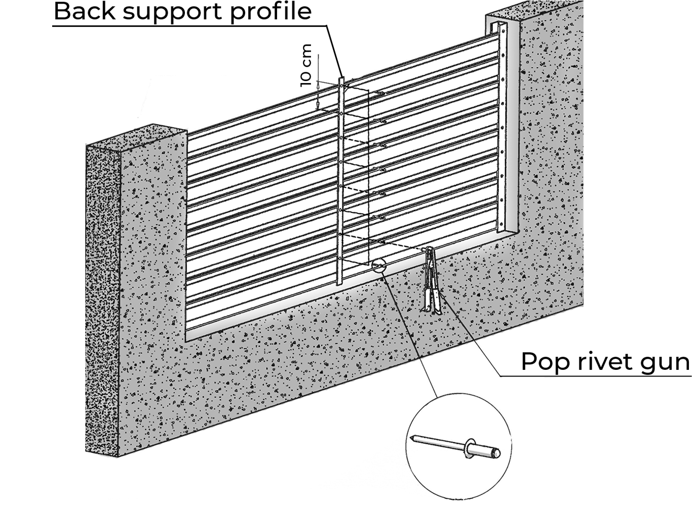
After finishing the drilling process, align the fixing holes of the Back Support Profile with those of the Blind Profiles.

Insert the pop-rivet into the pliers / rivet gun. Place the Pliers / Rivet Gun perpendicular to the hole and rivet them in the fixing points drilled in the previous step.

Hold the Back Support Profile firmly in place throughout the drilling process to avoid its repositioning.

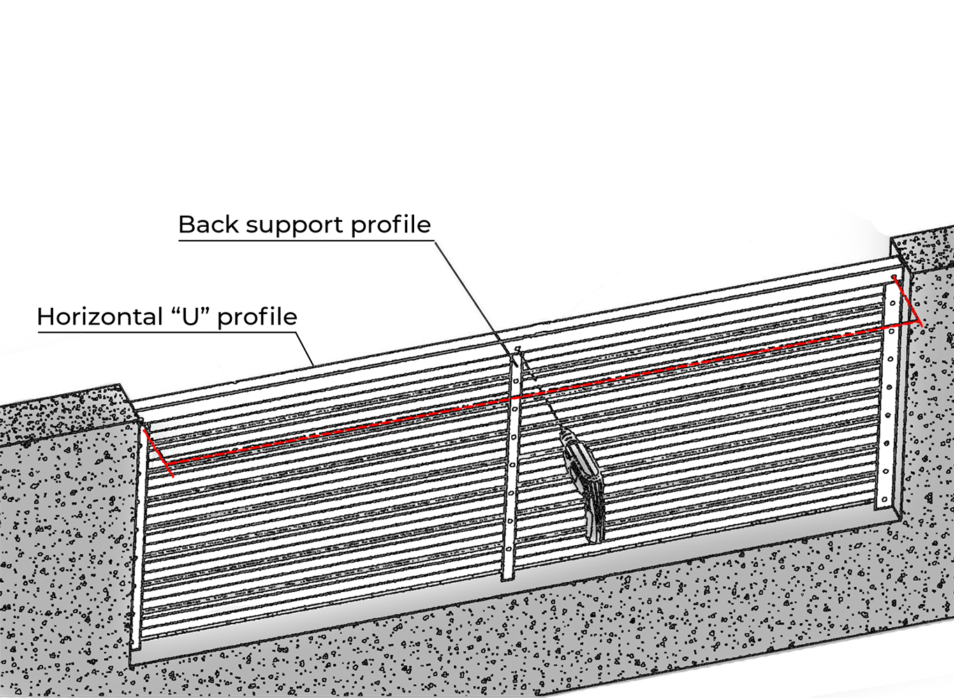
step 7 INSTALLATION OF THE HORIZONTAL “U” PROFILE

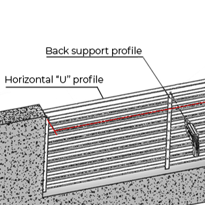
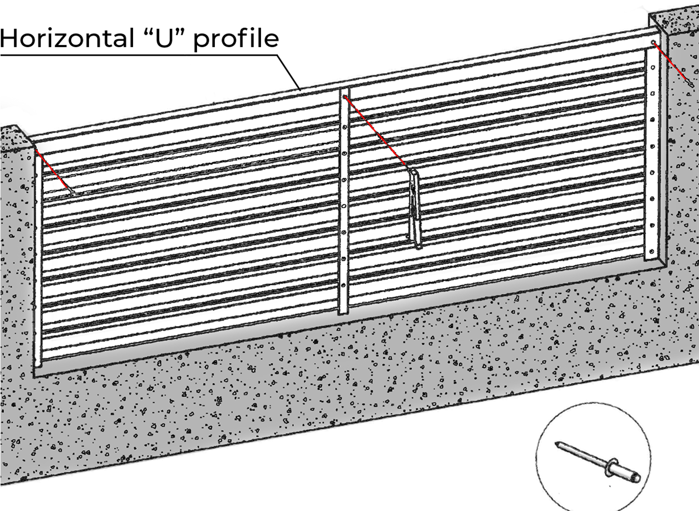
Position the horizontal “U” profile with the opening facing downwards, covering the ends of the vertical “U” profiles and the back support profile.

Using a drill with a ⌀ 5 metal bit, drill simultaneously:

  • the horizontal “U” profile and the vertical “U” profiles in 4 fixing points: 2 in the front (left and right) and 2 in the back (left and right);

  • the horizontal “U” profile and the back support profile in one fixing point.

Keep the profiles firmly in place throughout the drilling process to avoid their repositioning.
step 8 INSTALLATION OF THE HORIZONTAL “U” PROFILE

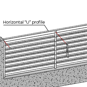
After finishing the drilling process, align the fixing holes of the Horizontal "U" Profile with those of the Vertical "U" Profiles and the Back Support Profile.

Insert the pop-rivet into the rivet gun. Place the Rivet Gun perpendicular to the hole and rivet them in the fixing points drilled in the previous step.

Keep the profiles firmly in place, throughout the riveting process, to avoid their repositioning.